Ethernet
Ethernet

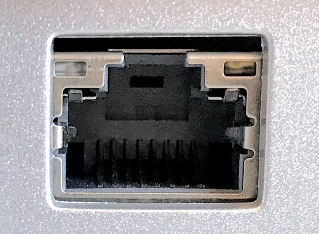
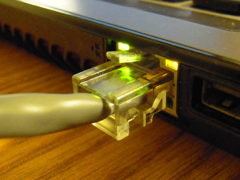
An Ethernet over twisted pair port
Ethernet /ˈiːθərnɛt/ is a family of computer networking technologies commonly used in local area networks (LAN), metropolitan area networks (MAN) and wide area networks (WAN).[13] It was commercially introduced in 1980 and first standardized in 1983 as IEEE 802.3, and has since retained a good deal of backward compatibility and been refined to support higher bit rates and longer link distances. Over time, Ethernet has largely replaced competing wired LAN technologies such as Token Ring, FDDI and ARCNET.
The original 10BASE5 Ethernet uses coaxial cable as a shared medium, while the newer Ethernet variants use twisted pair and fiber optic links in conjunction with switches. Over the course of its history, Ethernet data transfer rates have been increased from the original 2.94 megabits per second (Mbit/s)[14] to the latest 400 gigabits per second (Gbit/s). The Ethernet standards comprise several wiring and signaling variants of the OSI physical layer in use with Ethernet.
Systems communicating over Ethernet divide a stream of data into shorter pieces called frames. Each frame contains source and destination addresses, and error-checking data so that damaged frames can be detected and discarded; most often, higher-layer protocols trigger retransmission of lost frames. As per the OSI model, Ethernet provides services up to and including the data link layer.[15] The 48-bit MAC address was adopted by other IEEE 802 networking standards, including IEEE 802.11 Wi-Fi, as well as by FDDI, and EtherType values are also used in Subnetwork Access Protocol (SNAP) headers.
Ethernet is widely used in homes and industry.
The Internet Protocol is commonly carried over Ethernet and so it is considered one of the key technologies that make up the Internet.
History
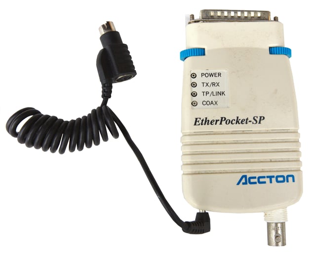
Accton Etherpocket-SP parallel port Ethernet adapter (circa 1990). Supports both coaxial (10BASE2) and twisted pair (10BASE-T) cables. Power is drawn from a PS/2 port passthrough cable.
Ethernet was developed at Xerox PARC between 1973 and 1974.[16][17] It was inspired by ALOHAnet, which Robert Metcalfe had studied as part of his PhD dissertation.[18] The idea was first documented in a memo that Metcalfe wrote on May 22, 1973, where he named it after the luminiferous aether once postulated to exist as an "omnipresent, completely-passive medium for the propagation of electromagnetic waves."[16][19][20] In 1975, Xerox filed a patent application listing Metcalfe, David Boggs, Chuck Thacker, and Butler Lampson as inventors.[21] In 1976, after the system was deployed at PARC, Metcalfe and Boggs published a seminal paper.[22][1] Yogen Dalal,[24] Ron Crane, Bob Garner, and Roy Ogus facilitated the upgrade from the original 2.94 Mbit/s protocol to the 10 Mbit/s protocol, which was released to the market in 1980.[25]
Metcalfe left Xerox in June 1979 to form 3Com.[16][26] He convinced Digital Equipment Corporation (DEC), Intel, and Xerox to work together to promote Ethernet as a standard. As part of that process Xerox agreed to relinquish their 'Ethernet' trademark.[27] The first standard was published on September 30, 1980 as "The Ethernet, A Local Area Network. Data Link Layer and Physical Layer Specifications". This so-called DIX standard (Digital Intel Xerox) specified 10 Mbit/s Ethernet, with 48-bit destination and source addresses and a global 16-bit Ethertype-type field.[28] Version 2 was published in November, 1982[29] and defines what has become known as Ethernet II. Formal standardization efforts proceeded at the same time and resulted in the publication of IEEE 802.3 on June 23, 1983.[30]
Ethernet initially competed with Token Ring and other proprietary protocols. Ethernet was able to adapt to market realities and shift to inexpensive thin coaxial cable and then ubiquitous twisted pair wiring. By the end of the 1980s, Ethernet was clearly the dominant network technology.[16] In the process, 3Com became a major company. 3Com shipped its first 10 Mbit/s Ethernet 3C100 NIC in March 1981, and that year started selling adapters for PDP-11s and VAXes, as well as Multibus-based Intel and Sun Microsystems computers.[31] [666666] This was followed quickly by DEC's Unibus to Ethernet adapter, which DEC sold and used internally to build its own corporate network, which reached over 10,000 nodes by 1986, making it one of the largest computer networks in the world at that time.[32] An Ethernet adapter card for the IBM PC was released in 1982, and, by 1985, 3Com had sold 100,000.[26] Parallel port based Ethernet adapters were produced for a time, with drivers for DOS and Windows. By the early 1990s, Ethernet became so prevalent that it was a must-have feature for modern computers, and Ethernet ports began to appear on some PCs and most workstations. This process was greatly sped up with the introduction of 10BASE-T and its relatively small modular connector, at which point Ethernet ports appeared even on low-end motherboards.
Since then, Ethernet technology has evolved to meet new bandwidth and market requirements.[33] In addition to computers, Ethernet is now used to interconnect appliances and other personal devices.[16] As Industrial Ethernet it is used in industrial applications and is quickly replacing legacy data transmission systems in the world's telecommunications networks.[34] By 2010, the market for Ethernet equipment amounted to over $16 billion per year.[35]
Standardization
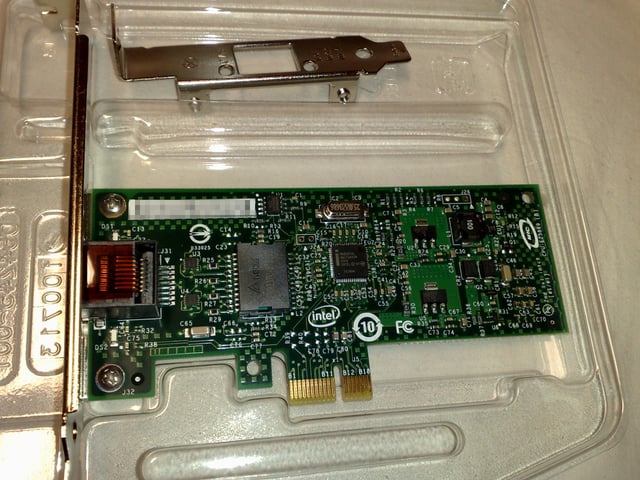
An Intel 82574L Gigabit Ethernet NIC, PCI Express ×1 card
In February 1980, the Institute of Electrical and Electronics Engineers (IEEE) started project 802 to standardize local area networks (LAN).[26][36] The "DIX-group" with Gary Robinson (DEC), Phil Arst (Intel), and Bob Printis (Xerox) submitted the so-called "Blue Book" CSMA/CD specification as a candidate for the LAN specification.[28] In addition to CSMA/CD, Token Ring (supported by IBM) and Token Bus (selected and henceforward supported by General Motors) were also considered as candidates for a LAN standard. Competing proposals and broad interest in the initiative led to strong disagreement over which technology to standardize. In December 1980, the group was split into three subgroups, and standardization proceeded separately for each proposal.[26]
Delays in the standards process put at risk the market introduction of the Xerox Star workstation and 3Com's Ethernet LAN products. With such business implications in mind, David Liddle (General Manager, Xerox Office Systems) and Metcalfe (3Com) strongly supported a proposal of Fritz Röscheisen (Siemens Private Networks) for an alliance in the emerging office communication market, including Siemens' support for the international standardization of Ethernet (April 10, 1981). Ingrid Fromm, Siemens' representative to IEEE 802, quickly achieved broader support for Ethernet beyond IEEE by the establishment of a competing Task Group "Local Networks" within the European standards body ECMA TC24. On March 1982, ECMA TC24 with its corporate members reached an agreement on a standard for CSMA/CD based on the IEEE 802 draft.[31] [666666] Because the DIX proposal was most technically complete and because of the speedy action taken by ECMA which decisively contributed to the conciliation of opinions within IEEE, the IEEE 802.3 CSMA/CD standard was approved in December 1982.[26] IEEE published the 802.3 standard as a draft in 1983 and as a standard in 1985.[37]
Approval of Ethernet on the international level was achieved by a similar, cross-partisan action with Fromm as the liaison officer working to integrate with International Electrotechnical Commission (IEC) Technical Committee 83 (TC83) and International Organization for Standardization (ISO) Technical Committee 97 Sub Committee 6 (TC97SC6). The ISO 8802-3 standard was published in 1989.[38]
Evolution
Ethernet has evolved to include higher bandwidth, improved medium access control methods, and different physical media. The coaxial cable was replaced with point-to-point links connected by Ethernet repeaters or switches.[39]
Ethernet stations communicate by sending each other data packets: blocks of data individually sent and delivered. As with other IEEE 802 LANs, each Ethernet station is given a 48-bit MAC address. The MAC addresses are used to specify both the destination and the source of each data packet. Ethernet establishes link-level connections, which can be defined using both the destination and source addresses. On reception of a transmission, the receiver uses the destination address to determine whether the transmission is relevant to the station or should be ignored. A network interface normally does not accept packets addressed to other Ethernet stations.[2] Adapters come programmed with a globally unique address.[3]
An EtherType field in each frame is used by the operating system on the receiving station to select the appropriate protocol module (e.g., an Internet Protocol version such as IPv4). Ethernet frames are said to be self-identifying, because of the EtherType field. Self-identifying frames make it possible to intermix multiple protocols on the same physical network and allow a single computer to use multiple protocols together.[40] Despite the evolution of Ethernet technology, all generations of Ethernet (excluding early experimental versions) use the same frame formats.[41] Mixed-speed networks can be built using Ethernet switches and repeaters supporting the desired Ethernet variants.[42]
Due to the ubiquity of Ethernet, the ever-decreasing cost of the hardware needed to support it, and the reduced panel space needed by twisted pair Ethernet, most manufacturers now build Ethernet interfaces directly into PC motherboards, eliminating the need for installation of a separate network card.[43]
Shared media
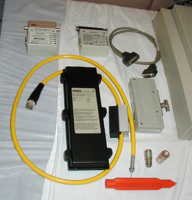
Older Ethernet equipment.
Ethernet was originally based on the idea of computers communicating over a shared coaxial cable acting as a broadcast transmission medium.
The method used was similar to those used in radio systems,[4] with the common cable providing the communication channel likened to the Luminiferous aether in 19th century physics, and it was from this reference that the name "Ethernet" was derived.[44]
Original Ethernet's shared coaxial cable (the shared medium) traversed a building or campus to every attached machine.
A scheme known as carrier sense multiple access with collision detection (CSMA/CD) governed the way the computers shared the channel. This scheme was simpler than competing Token Ring or Token Bus technologies.[5] Computers are connected to an Attachment Unit Interface (AUI) transceiver, which is in turn connected to the cable (with thin Ethernet the transceiver is integrated into the network adapter). While a simple passive wire is highly reliable for small networks, it is not reliable for large extended networks, where damage to the wire in a single place, or a single bad connector, can make the whole Ethernet segment unusable.[6]
Through the first half of the 1980s, Ethernet's 10BASE5 implementation used a coaxial cable 0.375 inches (9.5 mm) in diameter, later called "thick Ethernet" or "thicknet". Its successor, 10BASE2, called "thin Ethernet" or "thinnet", used the RG-58 coaxial cable. The emphasis was on making installation of the cable easier and less costly.[45] [666666]
Since all communication happens on the same wire, any information sent by one computer is received by all, even if that information is intended for just one destination.[7] The network interface card interrupts the CPU only when applicable packets are received: the card ignores information not addressed to it.[2] Use of a single cable also means that the data bandwidth is shared, such that, for example, available data bandwidth to each device is halved when two stations are simultaneously active.[46]
A collision happens when two stations attempt to transmit at the same time.
They corrupt transmitted data and require stations to re-transmit.
The lost data and re-transmission reduces throughput.
In the worst case, where multiple active hosts connected with maximum allowed cable length attempt to transmit many short frames, excessive collisions can reduce throughput dramatically.
However, a Xerox report in 1980 studied performance of an existing Ethernet installation under both normal and artificially generated heavy load. The report claimed that 98% throughput on the LAN was observed.[47] This is in contrast with token passing LANs (Token Ring, Token Bus), all of which suffer throughput degradation as each new node comes into the LAN, due to token waits. This report was controversial, as modeling showed that collision-based networks theoretically became unstable under loads as low as 37% of nominal capacity. Many early researchers failed to understand these results. Performance on real networks is significantly better.[48]
In a modern Ethernet, the stations do not all share one channel through a shared cable or a simple repeater hub; instead, each station communicates with a switch, which in turn forwards that traffic to the destination station. In this topology, collisions are only possible if station and switch attempt to communicate with each other at the same time, and collisions are limited to this link. Furthermore, the 10BASE-T standard introduced a full duplex mode of operation which became common with Fast Ethernet and the de facto standard with Gigabit Ethernet. In full duplex, switch and station can send and receive simultaneously, and therefore modern Ethernets are completely collision-free.
Repeaters and hubs
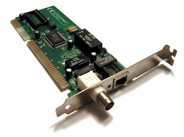
A 1990s ISA network interface card supporting both coaxial-cable-based 10BASE2 (BNC connector, left) and twisted pair-based 10BASE-T (8P8C connector, right)
For signal degradation and timing reasons, coaxial Ethernet segments have a restricted size.[49] Somewhat larger networks can be built by using an Ethernet repeater. Early repeaters had only two ports, allowing, at most, a doubling of network size. Once repeaters with more than two ports became available, it was possible to wire the network in a star topology. Early experiments with star topologies (called "Fibernet") using optical fiber were published by 1978.[50]
Shared cable Ethernet is always hard to install in offices because its bus topology is in conflict with the star topology cable plans designed into buildings for telephony.
Modifying Ethernet to conform to twisted pair telephone wiring already installed in commercial buildings provided another opportunity to lower costs, expand the installed base, and leverage building design, and, thus, twisted-pair Ethernet was the next logical development in the mid-1980s.
Ethernet on unshielded twisted-pair cables (UTP) began with StarLAN at 1 Mbit/s in the mid-1980s. In 1987 SynOptics introduced the first twisted-pair Ethernet at 10 Mbit/s in a star-wired cabling topology with a central hub, later called LattisNet.[26][51][52] These evolved into 10BASE-T, which was designed for point-to-point links only, and all termination was built into the device. This changed repeaters from a specialist device used at the center of large networks to a device that every twisted pair-based network with more than two machines had to use. The tree structure that resulted from this made Ethernet networks easier to maintain by preventing most faults with one peer or its associated cable from affecting other devices on the network.
Despite the physical star topology and the presence of separate transmit and receive channels in the twisted pair and fiber media, repeater-based Ethernet networks still use half-duplex and CSMA/CD, with only minimal activity by the repeater, primarily generation of the jam signal in dealing with packet collisions. Every packet is sent to every other port on the repeater, so bandwidth and security problems are not addressed. The total throughput of the repeater is limited to that of a single link, and all links must operate at the same speed.
Bridging and switching
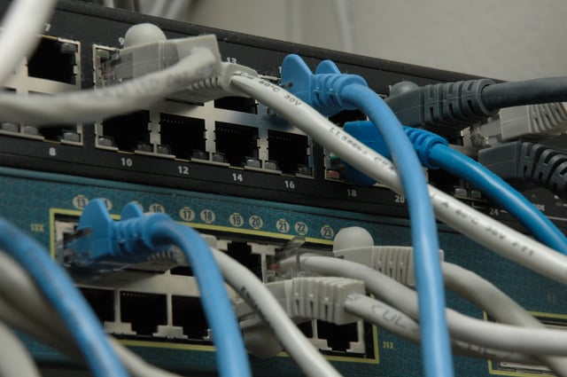
Patch cables with patch fields of two Ethernet switches
While repeaters can isolate some aspects of Ethernet segments, such as cable breakages, they still forward all traffic to all Ethernet devices. The entire network is one collision domain, and all hosts have to be able to detect collisions anywhere on the network. This limits the number of repeaters between the farthest nodes and creates practical limits on how many machines can communicate on an Ethernet network. Segments joined by repeaters have to all operate at the same speed, making phased-in upgrades impossible.
To alleviate these problems, bridging was created to communicate at the data link layer while isolating the physical layer.
With bridging, only well-formed Ethernet packets are forwarded from one Ethernet segment to another; collisions and packet errors are isolated.
At initial startup, Ethernet bridges work somewhat like Ethernet repeaters, passing all traffic between segments.
By observing the source addresses of incoming frames, the bridge then builds an address table associating addresses to segments.
Once an address is learned, the bridge forwards network traffic destined for that address only to the associated segment, improving overall performance.
Broadcast traffic is still forwarded to all network segments. Bridges also overcome the limits on total segments between two hosts and allow the mixing of speeds, both of which are critical to incremental deployment of faster Ethernet variants.
In 1989, the networking company Kalpana[9] introduced their EtherSwitch, the first Ethernet switch.[10] Early switches such as this used cut-through switching where only the header of the incoming packet is examined before it is either dropped or forwarded to another segment.[53] This reduces the forwarding latency. One drawback of this method is that it does not readily allow a mixture of different link speeds. Another is that packets that have been corrupted are still propagated through the network. The eventual remedy for this was a return to the original store and forward approach of bridging, where the packet is read into a buffer on the switch in its entirety, its frame check sequence verified and only then packet is forwarded. This process is typically done using application-specific integrated circuits allowing packets to be forwarded at wire speed.
When a twisted pair or fiber link segment is used and neither end is connected to a repeater, full-duplex Ethernet becomes possible over that segment. In full-duplex mode, both devices can transmit and receive to and from each other at the same time, and there is no collision domain. This doubles the aggregate bandwidth of the link and is sometimes advertised as double the link speed (for example, 200 Mbit/s for Fast Ethernet).[11] The elimination of the collision domain for these connections also means that all the link's bandwidth can be used by the two devices on that segment and that segment length is not limited by the need for correct collision detection.
Since packets are typically delivered only to the port they are intended for, traffic on a switched Ethernet is less public than on shared-medium Ethernet.
Despite this, switched Ethernet should still be regarded as an insecure network technology, because it is easy to subvert switched Ethernet systems by means such as ARP spoofing and MAC flooding.
The bandwidth advantages, the improved isolation of devices from each other, the ability to easily mix different speeds of devices and the elimination of the chaining limits inherent in non-switched Ethernet have made switched Ethernet the dominant network technology.[54]
Advanced networking
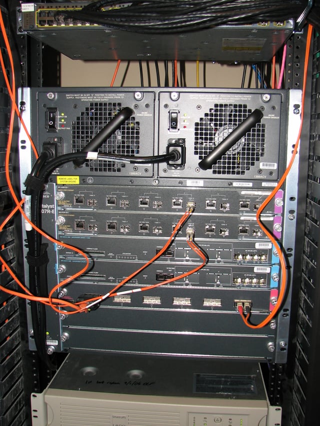
A core Ethernet switch
Simple switched Ethernet networks, while a great improvement over repeater-based Ethernet, suffer from single points of failure, attacks that trick switches or hosts into sending data to a machine even if it is not intended for it, scalability and security issues with regard to switching loops, broadcast radiation and multicast traffic, and bandwidth choke points where a lot of traffic is forced down a single link.
Advanced networking features in switches use shortest path bridging (SPB) or the spanning-tree protocol (STP) to maintain a loop-free, meshed network, allowing physical loops for redundancy (STP) or load-balancing (SPB). Advanced networking features also ensure port security, provide protection features such as MAC lockdown and broadcast radiation filtering, use virtual LANs to keep different classes of users separate while using the same physical infrastructure, employ multilayer switching to route between different classes, and use link aggregation to add bandwidth to overloaded links and to provide some redundancy.
Shortest path bridging includes the use of the link-state routing protocol IS-IS to allow larger networks with shortest path routes between devices. In 2012, it was stated by David Allan and Nigel Bragg, in 802.1aq Shortest Path Bridging Design and Evolution: The Architect's Perspective that shortest path bridging is one of the most significant enhancements in Ethernet's history.[55]
Ethernet has replaced InfiniBand as the most popular system interconnect of TOP500 supercomputers.[56]
Varieties
The Ethernet physical layer evolved over a considerable time span and encompasses coaxial, twisted pair and fiber-optic physical media interfaces, with speeds from 10 Mbit/s to 100 Gbit/s, with 400 Gbit/s expected by 2018.[57] The first introduction of twisted-pair CSMA/CD was StarLAN, standardized as 802.3 1BASE5.[58] While 1BASE5 had little market penetration, it defined the physical apparatus (wire, plug/jack, pin-out, and wiring plan) that would be carried over to 10BASE-T.
The most common forms used are 10BASE-T, 100BASE-TX, and 1000BASE-T. All three use twisted pair cables and 8P8C modular connectors. They run at 10 Mbit/s, 100 Mbit/s, and 1 Gbit/s, respectively.
Fiber optic variants of Ethernet are also very common in larger networks, offering high performance, better electrical isolation and longer distance (tens of kilometers with some versions). In general, network protocol stack software will work similarly on all varieties.
Frame structure
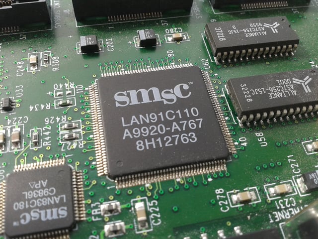
A close-up of the SMSC LAN91C110 (SMSC 91x) chip, an embedded Ethernet chip.
In IEEE 802.3, a datagram is called a packet or frame. Packet is used to describe the overall transmission unit and includes the preamble, start frame delimiter (SFD) and carrier extension (if present).[12] The frame begins after the start frame delimiter with a frame header featuring source and destination MAC addresses and the EtherType field giving either the protocol type for the payload protocol or the length of the payload. The middle section of the frame consists of payload data including any headers for other protocols (for example, Internet Protocol) carried in the frame. The frame ends with a 32-bit cyclic redundancy check, which is used to detect corruption of data in transit.[59] [666666] Notably, Ethernet packets have no time-to-live field, leading to possible problems in the presence of a switching loop.
Autonegotiation
Autonegotiation is the procedure by which two connected devices choose common transmission parameters, e.g. speed and duplex mode.
Autonegotiation is an optional feature, first introduced with 100BASE-TX, while it is also backward compatible with 10BASE-T.
Autonegotiation is mandatory for 1000BASE-T and faster.
Error conditions
Switching loop
A switching loop or bridge loop occurs in computer networks when there is more than one Layer 2 (OSI model) path between two endpoints (e.g. multiple connections between two network switches or two ports on the same switch connected to each other). The loop creates broadcast storms as broadcasts and multicasts are forwarded by switches out every port, the switch or switches will repeatedly rebroadcast the broadcast messages flooding the network. Since the Layer 2 header does not support a time to live
A physical topology that contains switching or bridge loops is attractive for redundancy reasons, yet a switched network must not have loops.
The solution is to allow physical loops, but create a loop-free logical topology using the shortest path bridging (SPB) protocol or the older spanning tree protocols (STP) on the network switches.
Jabber
A node that is sending longer than the maximum transmission window for an Ethernet packet is considered to be jabbering. Depending on the physical topology, jabber detection and remedy differ somewhat.
An MAU is required to detect and stop abnormally long transmission from the DTE (longer than 20–150 ms) in order to prevent permanent network disruption.[60]
On an electrically shared medium (10BASE5, 10BASE2, 1BASE5), jabber can only be detected by each end node, stopping reception.
No further remedy is possible.[61]
A repeater/repeater hub uses a jabber timer that ends retransmission to the other ports when it expires.
The timer runs for 25,000 to 50,000 bit times for 1 Mbit/s,[62] 40,000 to 75,000 bit times for 10 and 100 Mbit/s,[63][64] and 80,000 to 150,000 bit times for 1 Gbit/s.[65] Jabbering ports are partitioned off the network until a carrier is no longer detected.[66]
End nodes utilizing a MAC layer will usually detect an oversized Ethernet frame and cease receiving.
A bridge/switch will not forward the frame.[67]
A non-uniform frame size configuration in the network using jumbo frames may be detected as jabber by end nodes.
A packet detected as jabber by an upstream repeater and subsequently cut off has an invalid frame check sequence and is dropped.
Runt frames
Runts
See also
5-4-3 rule
Chaosnet
Ethernet crossover cable
Fiber media converter
List of device bit rates
LocalTalk
Metro Ethernet
PHY (chip)
Point-to-point protocol over Ethernet (PPPoE)
Power over Ethernet (PoE)
Sneakernet
Wake-on-LAN (WoL)